Ok so I run down to my local Ford dealer and I order a new coil pack, as the old one is pretty beat up and chipped.
I specifically mention I want the one with the SQUARE connector port, post 2008, so it matches my Webcon harness.
I pay R850 because it has to be ordered special.
Cool, I wait for a day and I get a call from them to say my coil pack has arrived.
Yeah, you guessed it, it is the old one with the oval connector.
The confusion came in because I asked for a Coolant Temp Sensor for a 2002 Mondeo 2.0l and she ordered the coil pack from that model as well.
Fortunately the Webcon harness comes with an oval connector (as a spare), so I spent the evening cutting off the new-style square connector and attaching the old-style oval one to the harness.
I attached the wires to the new old-style oval connector the same way they were connected to the old new-style square connector.
The worst that can happen is that the engine will not start because the spark is being delivered at BDC instead of TDC. Swop the 2 wires around I am back in business.
Doing some internet research I found that when they changed over the coil pack from the old oval type to the new square type the orientation of the wires was indeed changed over, so I disassembled my new old-style oval connector and swopped the wires. These things are not meant to be taken apart once they are put together with the result that the metal contacts are a bit munched. I will try and source a new old-style oval connector from Ford.
Confused yet??
With my luck they will send me a new new-style square one, instead of a new old-style oval one.....
Quick note to everyone reading or accessing this blog - PLEASE LEAVE COMMENTS IF YOU LIKE OR DO NOT LIKE WHAT YOU SEE AND READ!!
I see my count is on the rise - even from folks in Alaska.....?? I am trying to keep it light but unfortunately the content does require some technical talk!!
Wednesday, 19 September 2012
Sunday, 16 September 2012
The Cooling System
I've decided to create my own cooling system layout. In a previous post I made mention of hanging the pump off the engine. I changed that idea to making a bracket and attaching that to the chassis and hanging the pump off that.
After that the rest was simple. If the bracket shows signs of fatigue I will make it out of steel.

The top section from the rail to the radiator was even simpler. I now need a couple of banjo fittings and fitting the header tank and I am done with the cooling system.


After that the rest was simple. If the bracket shows signs of fatigue I will make it out of steel.


I took time out to dummy-fit the throttle bodies, and found out my carefully assembled linkage was fouling the left top cross-member. I reversed it and now the linkage operates smoothly. I cannot fit these yet as she must go to the paint shop first.
I also bought some black paint for the headers and the cam cover.
Sunday, 9 September 2012
Time out for a Rant
Yep, you read right I am downright pissed.
I am struggling with this cooling system. I seem to have been supplied with enough hoses, but there is no indication of what fits where or what connects to what.
On top of that I have gone with a water rail, which deletes at least 2 hoses and one pipe, and I have identified which pipe and what hoses they are - I will have to make up my own layout for that - but as for the rest it's a total mystery.
I also went with the electric water pump, and I spent the morning just staring into the well in front of the engine trying to figger where the water pump and its associated mounting hardware might fit. I could not see it.
Which brings me to my point. How in hell can Birkin put a product onto the market without detailed assembly instructions???
I'm not sure if Birkin realise what liability they are exposing themselves to. Would you travel in a car that was assembled by people who had no instructions on how to put it together?
They say they have the "Build Doctor" BIG FRICKIN' DEAL!!! The doctor starts out all very well but it looks like they got bored with it half way through and gave up.
The section does not cover (inter alia)
The Independent Rear Suspension
The Differential
Installing the Engine (various types)
The Cooling System (Fan, plumbing, fan switch, header tank, water pump)
The Exhaust system
It's farcical.
And the bits that are covered are out of date.
Sure it is a car for enthusiasts built by enthusiasts but not everyone is mechanically savvy to the degree that they can build it to factory spec as was intended. I place myself into that category.
I do realise that most of the assembly is self-evident, but even so...
When I started this I was assured that they (Birkin) had all the drawings and pictures needed on computer, and they were available on request.
Three months down the line and R200 000+ later I am convinced that is not true.
So what did I do today?
I fitted the horn, and the cooling fan and water-pump relays. And not even the horn fitted where I thought it was supposed to. I had to suss that one out for myself.
I then decided to man up and design my own water pump installation. You will see above the water pump mounting slot there is the open hole left by the
old Mondeo engine mount stud.

old Mondeo engine mount stud.


I am going to hang a M12 stud out the bottom and fabricate a bracket that will let the pump hang off that. A lot of the pump's weight will be taken up by the hoses. I will have to get some rubber mounts to null out any engine vibration. My problem with this idea is that the pump is no longer at the lowest point of the system guaranteeing flooded suction, but it is low enough.

Thursday, 6 September 2012
The Water Rail and Exhaust Headers Completed
On Tuesday I had the rail welded up and it looks like a very neat job. I wanted to fit it that day but I had to go to Jo'burg on business and only came back today.
Cutting to the chase the headers were installed, tightened up with the supplied bolts (no studs) and the rail went on straight after with no issues.
It pays to fit and check before you fasten!


Finally I fitted the crank position sensor, using the jig, and fixing the damper with an M6 screw.

I had wanted to fit this while the engine was still on the engine stand, but I was worried it might get damaged in the installation - it is very exposed.
This weekend I will start piecing together the cooling system. This evening I tested the thermostat in a pot of boiling water (it works) and I also drilled a couple of 2mm holes in the thermostat's plunger as a bypass so that the electric pump doesn't cavitate while it is closed.
There are very few bits left to fit on this car - soon it will just be cosmetic stuff like the windscreen and the wipers.
Cutting to the chase the headers were installed, tightened up with the supplied bolts (no studs) and the rail went on straight after with no issues.
It pays to fit and check before you fasten!

Finally I fitted the crank position sensor, using the jig, and fixing the damper with an M6 screw.

I had wanted to fit this while the engine was still on the engine stand, but I was worried it might get damaged in the installation - it is very exposed.
This weekend I will start piecing together the cooling system. This evening I tested the thermostat in a pot of boiling water (it works) and I also drilled a couple of 2mm holes in the thermostat's plunger as a bypass so that the electric pump doesn't cavitate while it is closed.
There are very few bits left to fit on this car - soon it will just be cosmetic stuff like the windscreen and the wipers.
Sunday, 2 September 2012
The Water Rail and Exhaust Headers
This morning I wanted to install the Raceline water rail. It is a very nifty bit of kit that does away with long hoses and pipes to bring hot water from the back of the Duratec to the front.
My first move was to temporarily install the exhaust headers, just to see there were no issues with that bit of the work. I found that the two rear lower manifold studs would not go in, because of the chassis strut.

I had previously had the cylinder head modified to accept the water rail, but this was without the headers in place.

Then I removed the first three headers, leaving the last one in place, fitted the rail and saw immediately there was interference from the exhaust flange. Off came the rail, out came the header and I used a disc grinder to remove metal from the flange. This was a trial and error process, with at least 3 fittings before it fitted. Note the ever-present rubber mallet, this was especially useful to discover binding points. With everything put together, bash the rail a couple of times, and on disassembly, touching points show up on the aluminium. Grind them off, and retry.
I repeated this for the two middle headers, grinding away a bit at a time until the rail fitted. I used the die grinder to remove some from the rail as well.

The last header to fit was #1 cylinder, and this was the big one - a lot of metal had to go from the rail. There was a big flange cast right above the header.

I just removed enough to clear the header, there was about 3mm clearance. The rail will now go to the welding shop where they will place a circular aluminium disk in the top and weld it up for a good seal.

Just to make sure I fitted the rail plus the headers again and it is all a good fit.

I now wanted to fit the cooling hoses and the electric water pump, but I have no clue how the hoses run, especially with a water rail thrown into the mix. So that job will wait until Birkin supply me with some guidance.
My first move was to temporarily install the exhaust headers, just to see there were no issues with that bit of the work. I found that the two rear lower manifold studs would not go in, because of the chassis strut.
I had previously had the cylinder head modified to accept the water rail, but this was without the headers in place.
Then I removed the first three headers, leaving the last one in place, fitted the rail and saw immediately there was interference from the exhaust flange. Off came the rail, out came the header and I used a disc grinder to remove metal from the flange. This was a trial and error process, with at least 3 fittings before it fitted. Note the ever-present rubber mallet, this was especially useful to discover binding points. With everything put together, bash the rail a couple of times, and on disassembly, touching points show up on the aluminium. Grind them off, and retry.
I repeated this for the two middle headers, grinding away a bit at a time until the rail fitted. I used the die grinder to remove some from the rail as well.

The last header to fit was #1 cylinder, and this was the big one - a lot of metal had to go from the rail. There was a big flange cast right above the header.

I just removed enough to clear the header, there was about 3mm clearance. The rail will now go to the welding shop where they will place a circular aluminium disk in the top and weld it up for a good seal.

Just to make sure I fitted the rail plus the headers again and it is all a good fit.

I now wanted to fit the cooling hoses and the electric water pump, but I have no clue how the hoses run, especially with a water rail thrown into the mix. So that job will wait until Birkin supply me with some guidance.
Saturday, 1 September 2012
Engine Installation
The big day has arrived.
My first task of the day was to remove about 2mm from the outside of each flexible engine mount. This was easily done with an electric drill and an abrasive disc.
Next was the lift and this was horrendously difficult because while the dimensions were now fine, and we could get the left side M12 bolt in position, the right side was impossible to line up. So much so that we resorted to hammering in the bolt which resulted in a buggered thread. We replaced this with a M10 bolt just to take up the weight.
I re-attached the gearbox mount, and bolted on the sump guard cross member. This meant that if anything was to fail, it would result in a bent chassis and engine.
The engine was now supported by the left hand M12 bolt and the gear mounting, and the M10 bolt. Alastair gently let off the strain and ....she held!
Quickly I re-assessed my options: I re-arranged the sling so that it fastened to one central point at the front of the engine, seeing as it was fixed at the rear, and took the weight off the bolts holding the engine. I withdrew these, and also unscrewed the engine mount brackets for inspection. The right side one was totally chewed and ruined inside the flexible mount, and had to be cleaned up with a rat-tail file, so that the bolt could be inserted.
We then mounted the brackets on the chassis, and in turn, attached the brackets to the engine. Every cap-screw save the one went in - the front mounting point on the right side engine bracket is clearly out of line with the engine mounting hole by 2-3 mm.

The prop shaft was re-attached to the diff, and the reverse switch screwed into the gearbox.
The engine is now installed, and a major milestone met.

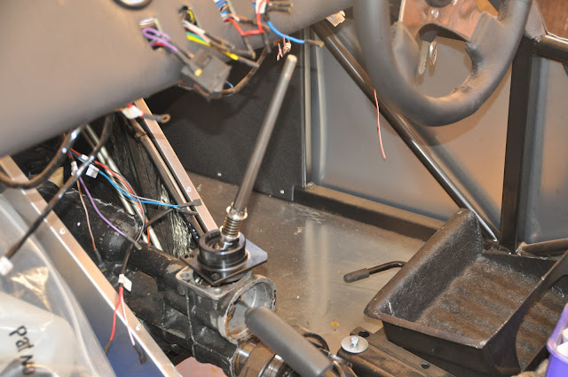
I also found my quick shift Quaife gear lever is about 3 inches too long.
Next is the cooling system and the water rail.
My first task of the day was to remove about 2mm from the outside of each flexible engine mount. This was easily done with an electric drill and an abrasive disc.
Next was the lift and this was horrendously difficult because while the dimensions were now fine, and we could get the left side M12 bolt in position, the right side was impossible to line up. So much so that we resorted to hammering in the bolt which resulted in a buggered thread. We replaced this with a M10 bolt just to take up the weight.
I re-attached the gearbox mount, and bolted on the sump guard cross member. This meant that if anything was to fail, it would result in a bent chassis and engine.
The engine was now supported by the left hand M12 bolt and the gear mounting, and the M10 bolt. Alastair gently let off the strain and ....she held!
Quickly I re-assessed my options: I re-arranged the sling so that it fastened to one central point at the front of the engine, seeing as it was fixed at the rear, and took the weight off the bolts holding the engine. I withdrew these, and also unscrewed the engine mount brackets for inspection. The right side one was totally chewed and ruined inside the flexible mount, and had to be cleaned up with a rat-tail file, so that the bolt could be inserted.
We then mounted the brackets on the chassis, and in turn, attached the brackets to the engine. Every cap-screw save the one went in - the front mounting point on the right side engine bracket is clearly out of line with the engine mounting hole by 2-3 mm.

The prop shaft was re-attached to the diff, and the reverse switch screwed into the gearbox.
The engine is now installed, and a major milestone met.


Next is the cooling system and the water rail.
Subscribe to:
Comments (Atom)